


Up to now, U-rings as rod seals and additional scrapers against the penetration of soil have been used in most pneumatic equipment (figure 40). Contrary to this conventional seal design, as a seal combination, the novel Kaco BILIP-P seal scraper elements fulfil the function of sealing at the piston rod and in the housing and also fulfil the function of the scraper (figure 41). In addition, they display the following


advantages:
- They can be replaced from the outside of the device
- Low space requirements
- Long service life
- Corrosion protection by means of a rubber jacket
BILIP-P seal scraper elements have completely moulded sealing lips with a rounded sealing edge and several ribs on their contact surface, the gaps of which are filled with grease before installation (refer to the description on page 5). This results in the favourable friction behaviour and high resistance to wear and tear. The gap between the sealing lip and scraper, which is also filled with grease, contributes towards the improvement of the slip behaviour and towards preventing the penetration of dirt. Thanks to this design of the dynamic sealing surface, the service life is also not
reduced in the case of lacking lubrication. Easy movement and starting force are also favourably influenced. BILIP-P elements can also be used for operation with oil-free air, which is being demanded more and more to prevent pollution because they are independent of external lubrication.
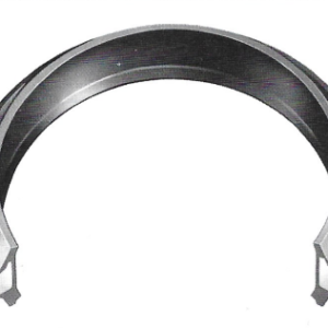
BILIP-P seal scraper elements are installed in a hole with the tolerance field H 10. It is supported at the rear by means of a round-wire circlip (DIN 7993, version B), which is held in a recess in the location hole. The rest surface of the BILIP element on the retaining ring is slanted. The angular metallic support element is rubber-covered on all sides for protection against corrosion. This is especially advantageous in the case of
operation with untreated and moist air.
The external diameter of BILIP-P seal scraper elements has been designed to enable easy insertion by hand into the location hole without special aids. The round-wire retaining ring can also be inserted by hand.
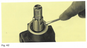
Removal is also simple. For removal of the retaining ring, the ring groove has an axial recess at one point so that it can be easily removed with a screwdriver (figure 42). The BILIP element can then be easily pushed off the location hole by means of slight pres-
sure impact, even if the piston rod is installed.
Technical data:
Pressure range ≤ 16 bar
Permissible sliding speed ≤ 1 m/s
Tolerances
dynamic (rod) H11
static (housing) H10
| Item number | d | D | H | d1 | e | f | R | R1 |
| QHLP8 • 16 RGU 01 | 8 | 16 | 6,7 | 17,6 | 0,9 | 1,5 | 0,9 | 4 |
| QHLP8 • 18RGU 01 | 8 | 18 | 7,5 | 19,6 | 0,9 | 1,5 | 0,9 | 4 |
| QHLP10 • 18RGU 01 | 10 | 18 | 7,5 | 19,6 | 0,9 | 1,5 | 0,9 | 4 |
| QHLP10 • 20RGU 01 | 10 | 20 | 7,7 | 22 | 1,1 | 1,8 | 1,1 | 4 |
| QHLP12 • 22RGU 01 | 12 | 22 | 7,7 | 24 | 1,1 | 1,8 | 1,1 | 4 |
| QHLP14 • 24RGU 01 | 14 | 24 | 7,7 | 26 | 1,1 | 1,8 | 1,1 | 4 |
| QHLP16 • 26RGU 01 | 16 | 26 | 7,7 | 28 | 1,1 | 1,8 | 1,1 | 5 |
| QHLP18 • 28RGU 01 | 18 | 28 | 7,7 | 30 | 1,1 | 1,8 | 1,1 | 5 |
| QHLP20 • 30RGU 01 | 20 | 30 | 7,7 | 32 | 1,1 | 1,8 | 1,1 | 5 |
| OHLP22 • 32RGU 01 | 22 | 32 | 8 | 34,5 | 1,4 | 2 | 1,4 | 7,5 |
| QHLP25 • 35RGU 01 | 25 | 35 | 8 | 37,5 | 1,4 | 2 | 1,4 | 7,5 |
| QHLP28 • 38RGU 01 | 28 | 38 | 8 | 40,5 | 1,4 | 2 | 1,4 | 7,5 |
| QHLP30 • 40RGU 01 | 30 | 40 | 8 | 42,5 | 1,4 | 2 | 1,4 | 7,5 |
| QHLP32 • 42RGU 01 | 32 | 42 | 8 | 44,5 | 1,4 | 2 | 1,4 | 7,5 |
| QHLP35 • 45RGU 01 | 35 | 45 | 8 | 47,5 | 1,4 | 2 | 1,4 | 7,5 |
| QHLP36 • 46RGU 01 | 36 | 46 | 8 | 48,5 | 1,4 | 2 | 1,4 | 7,5 |
| QHLP40 • 50RGU 01 | 40 | 50 | 8 | 52,5 | 1,4 | 2 | 1,4 | 7,5 |
| QHLP45 • 55RGU 01 | 45 | 55 | 8,6 | 58,2 | 1,8 | 2,5 | 1,8 | 10 |
| QHLP50 • 60RGU 01 | 50 | 60 | 8,6 | 63,2 | 1,8 | 2,5 | 1,8 | 10 |
| QHLP60 • 72RGU 01 | 60 | 72 | 9,6 | 75,2 | 1,8 | 2,5 | 1,8 | 10 |
| QHLP63 • 75RGU 01 | 63 | 75 | 9,6 | 78,2 | 1,8 | 2,5 | 1,8 | 10 |

Beoordelingen
Er zijn nog geen beoordelingen.