

Design:
Designed for use on one piece pistons, the seal assembly consists of a filled PTFE high performance outer sleeve, pre loaded and pressure energised by a precision moulded NBR element. These two components are protected from extrusion at either side by the fitting of two low friction plastic anti-extrusion rings making the seal highly resistant to shock loads as found in heavy duty mobile equipment. The housing dimensions are those used in standard metric J.I.S. cylinders.
| Maximum Pressure | ||||||
| Max Speed | Temp. Range | Temp. Range | ||||
| m/s | -30°C to 80°C | -30°C to 100°C | ||||
| 4 | 350 Bar | 280 Bar | ||||
| 2 | 500 Bar | 400 Bar | ||||
These range perameters are Maximum simultaneous conditions. Optimum service conditions are affected by temperature, speed, pressure, surface finish and extrusion gaps.
Refer to Appendix 1 for further information
| NBR Rubber | ||
| DIN | Hydraulic Fluid Description | °C |
| H | Mineral oil without additives | 100 |
| H-L | Mineral Fluid with anti corrosion and anti ageing additives | 100 |
| H-LP | Mineral oil as HL plus additives reducing wear, raising load | 100 |
| H-LPD | Mineral oil as H-LP but with detergents and dispersants | 100 |
| H-V | Mineral oil as H-LP plus improved viscosity temp. | 100 |
| HFA E | Emulsions of mineral oil in water. Water content 80-95% | 55 |
| HFA S | Synthetic oil in water. Water content 80-95% | 55 |
| HFB | Emulsions of water in mineral oil. Water content 40% | 60 |
| HFC | Aqueous polymer solutions. Water content 35% | 60 |
| HFD R | Phosphoric acid ester based | NS |
| HFD S | Chlorinated hydrocarbon based | NS |
| HFD T | Mixtures of HFD R and HFD S | NS |
| HEPG | Polyglycol based | NS |
| HETG | Vegetable Oil based | 60 |
| HEES | Fully synthetic ester based | NS |
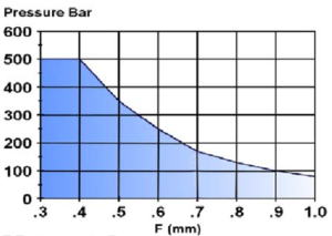
Note: Clearance gap F is the maximum permissable. i.e. gap completely on one side, in the temperature range of -30°C to 100°C The use of a suitably selected Claron bearing ring will effectively reduce the clearance gap F max. to a value closer to F/2 thus increasing the pressure capability of the seal.
Housing:
For surface finish and recommended lead in chamfers refer to the illustration below. For housing dimensions and machining tolerances refer to the catalogue page of selected seal. Refer to Appendix 4 for value of tolerance symbols.
Fitting:
For the seal to function correctly, it is important that care be taken in fitting the seal within its housing. For a detailed checklist, refer to Appendix 3.

| Part Number | +0,00 | +0,20 | Nominal | ||||||||||
| H9
ØD1 |
-0.20 Ød1 |
-0.00 L1 |
C | ||||||||||
| SPW 050 | 50 | 36 | 9,0 | 4,0 | |||||||||
| SPW 060 | 60 | 46 | 9,0 | 4,0 | |||||||||
| SPW 065 | 65 | 50 | 11,0 | 5,0 | |||||||||
| SPW 070 | 70 | 55 | 11,0 | 5,0 | |||||||||
| SPW 075 | 75 | 60 | 11,0 | 5,0 | |||||||||
| SPW 080 | 80 | 65 | 11,0 | 5,0 | |||||||||
| SPW 085 | 85 | 70 | 11,0 | 5,0 | |||||||||
| SPW 090 | 90 | 75 | 11,0 | 5,0 | |||||||||
| SPW 095 | 95 | 80 | 11,0 | 5,0 | |||||||||
| SPW 100 | 100 | 85 | 12,5 | 5,0 | |||||||||
| SPW 105 | 105 | 90 | 12,5 | 5,0 | |||||||||
| SPW 108 | 108 | 93 | 12,5 | 5,0 | |||||||||
| SPW 110 | 110 | 95 | 12,5 | 5,0 | |||||||||
| SPW 115 | 115 | 100 | 12,5 | 6,5 | |||||||||
| SPW 120 | 120 | 105 | 12,5 | 6,5 | |||||||||
| SPW 125 | 125 | 102 | 16,0 | 6,5 | |||||||||
| SPW 130 | 130 | 107 | 16,0 | 6,5 | |||||||||
| SPW 135 | 135 | 112 | 16,0 | 6,5 | |||||||||
| SPW 140 | 140 | 117 | 16,0 | 6,5 | |||||||||
| SPW 145 | 145 | 122 | 16,0 | 6,5 | |||||||||
| SPW 150 | 150 | 127 | 16,0 | 6,5 | |||||||||
| SPW 160 | 160 | 137 | 16,0 | 6,5 | |||||||||
| SPW 165 | 165 | 142 | 16,0 | 6,5 | |||||||||
| SPW 170 | 170 | 147 | 16,0 | 6,5 | |||||||||
| SPW 180 | 180 | 157 | 16,0 | 6,5 | |||||||||
| SPW 185 | 185 | 162 | 16,0 | 6,5 | |||||||||
| SPW 190 | 190 | 167 | 16,0 | 6,5 | |||||||||
| SPW 200 | 200 | 177 | 16,0 | 6,5 | |||||||||
| SPW 210 | 210 | 187 | 16,0 | 6,5 | |||||||||
| SPW 220 | 220 | 197 | 16,0 | 6,5 | |||||||||
| SPW 225 | 225 | 202 | 16,0 | 6,5 | |||||||||
| SPW 250 | 250 | 222 | 17,5 | 7,5 | |||||||||
Beoordelingen
Er zijn nog geen beoordelingen.